CNC milling
Prismatic components, machined faces, pockets, bores and interface features evaluated against geometry, material, quantity and inspection needs.
CUSTOM INDUSTRIAL COMPONENTS
True Blue connects drawings and project requirements with suitable manufacturing resources, process planning, quality expectations and repeat-supply needs.
MANUFACTURING SCOPE
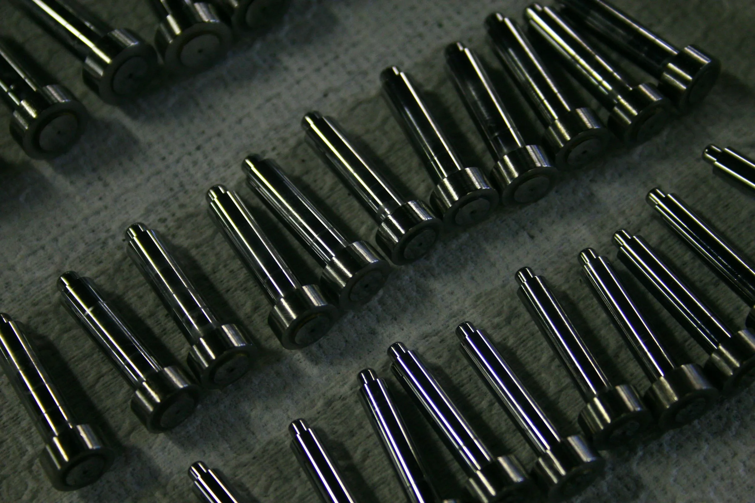
Geometry, material, quantity, critical features, downstream processes and inspection requirements are considered together. Capability and resource availability are confirmed for each project.
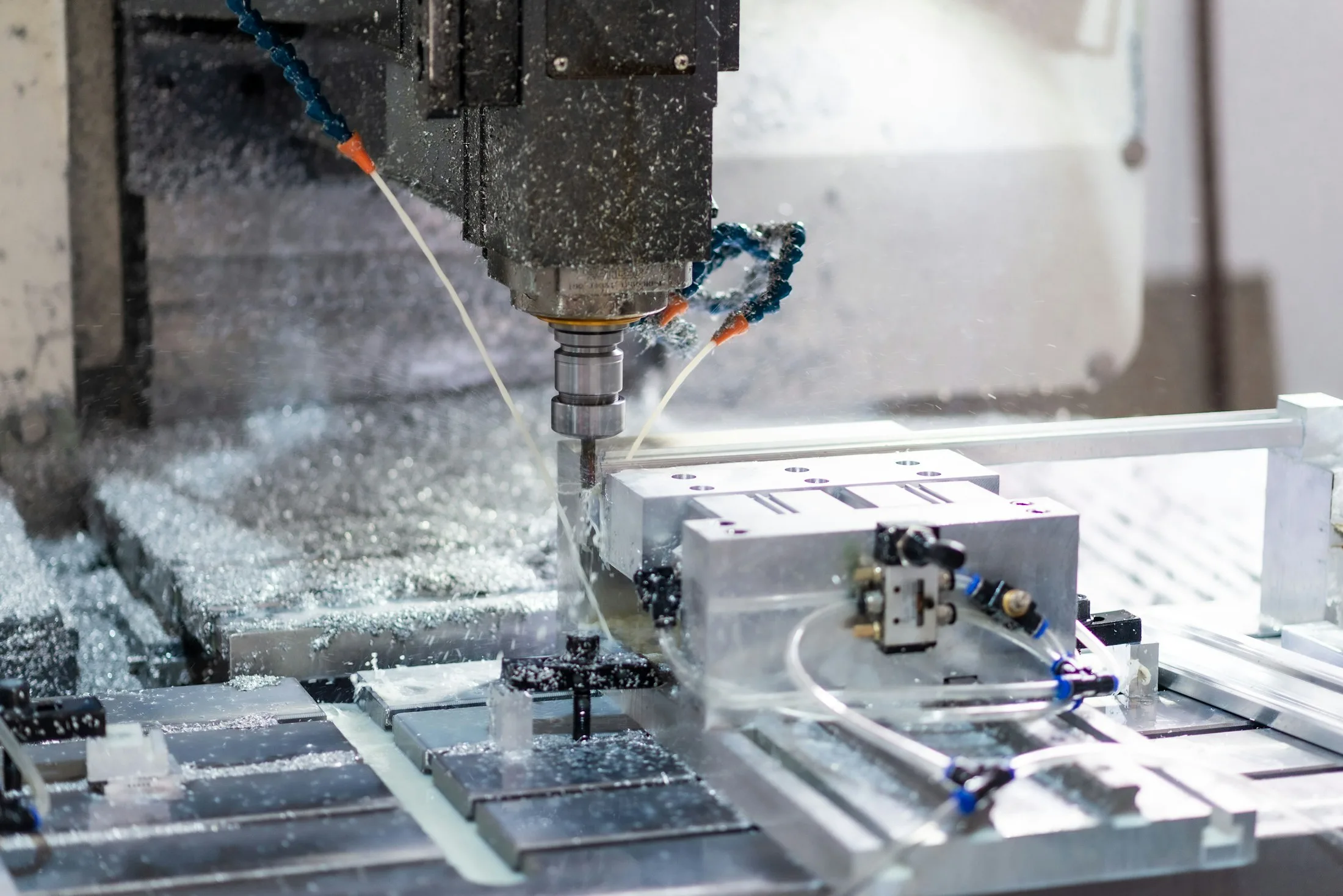
Prismatic components, machined faces, pockets, bores and interface features evaluated against geometry, material, quantity and inspection needs.
Shafts, sleeves, threaded parts and rotational features matched to an appropriate turning route and any required downstream operations.
Feature-specific grinding considered where flatness, cylindrical geometry, dimensional accuracy or surface finish requires it.
Applicable finishing, heat treatment, fabrication and assembly operations coordinated as part of the confirmed manufacturing route.
DRAWING + PROCESS REVIEW
A useful technical package separates confirmed requirements from assumptions. Drawing revision, material condition, tolerances, interfaces, finishes and inspection responsibilities should be aligned before the manufacturing route is released.
QUALITY PLANNING
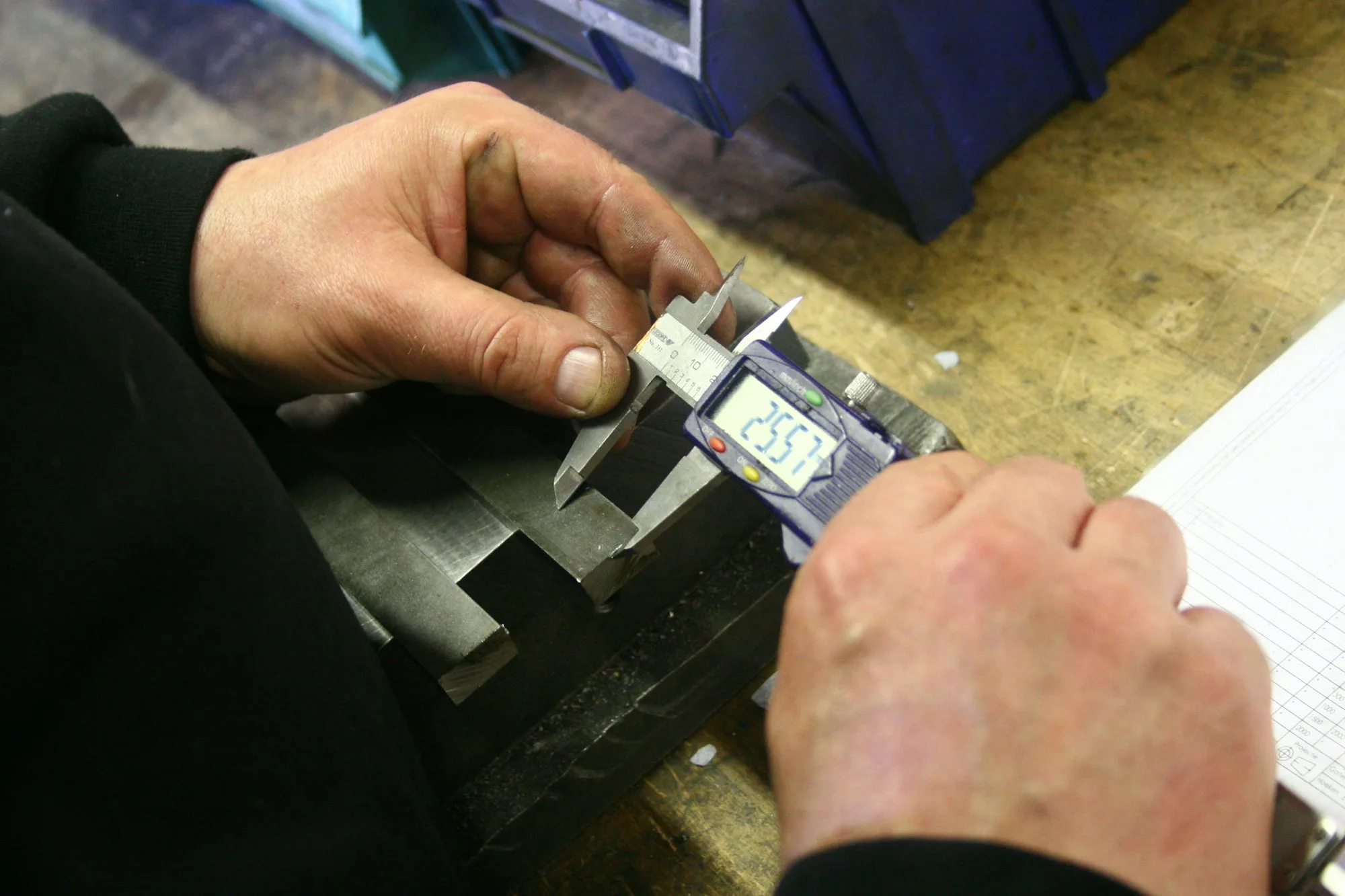
Tolerances down to ±0.005 mm for qualified features and applications.
Achievable tolerance depends on material, part size, geometry, manufacturing process, feature definition, and inspection requirements.
APPLICATION CONTEXT
Function, interfaces, operating conditions and repeat-supply expectations provide the context needed to define a suitable manufacturing and verification route.
Explore application considerationsLoad, operating environment, wear, interfaces and replacement cycles
Alignment, repeatability, weight, sensing and assembly interfaces
Groove geometry, mating surfaces, material, cleanliness and verification
Fit, interface control, sequence, documentation and packaging
START A PROJECT
Share the available drawing, model, material, quantity, critical features and quality requirements to begin a focused manufacturing evaluation.